
Dams – Special Foundation Works – Design Services
 3D Model of open trench, contour plot of total displacement
Bauer Spezialtiefbau supports the designer in different stages of project development regarding relevant foundation engineering techniques. State-of-the-art foundation engineering methods together with reliable software is used by experienced in-house designers to support clients and their engineers during preliminary stages and for the execution design.
Execution and Final Design
To carry out special foundation works, complete designs with all details are needed to ensure safe and smooth execution. Not only specific design calculations such as trench stability designs are provided, but also complete geotechnical project designs to establish the execution parameters of the various foundation engineering techniques in accordance with the client’s requirements. For dam rehabilitation projects the safety of the existing structure is considered to be of utmost importance for such designs.
Computation
 Model in plan view, contour plot of settlements
In addition to the standard design calculations such as the stability of the open trench during construction of a cut-off wall or slope stability considering the working loads during the execution of works on existing dams, special tasks are also performed regularly.
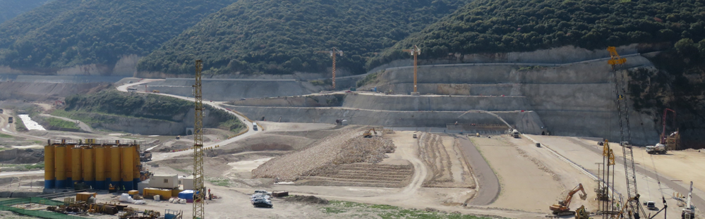
An actual example of such task is the Sylvenstein Project – where a trench was cut next to a recently completed panel. The required initial concrete strength in the panel was analyzed using the 3D-FEM tool PLAXIS. Both Fellenius' Method and the computed settlements method were used to assess the safety level of the system – see figures.
Documentation
Accuracy of workmanship and the verification of the special foundation works executed are vital to us. The as-built survey of each structural element is documented to be transferred into a structural as-built drawing as per project requirements. By entering all the measurement data into an illustrative quality system the exact properties and alignments of the diaphragm wall and the achievement of the minimum panel overlap can be confirmed – see figure below.
 As-built drawing of a completed cut off wall
 Primary Panel
 Secondary Panel