Lower Mae Ping

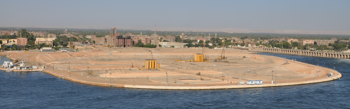
Lower Mae Ping dam is located in the Tak province. Approximately 400 kilometers north of Bangkok, the capital of Thailand.
The Lower Mae Ping dam was constructed at 5 km downstream of the Bhumibol dam along the Mae Ping river to ensure that the reversible pump / turbine generator of unit 8 can supply adequate power production as required. The dam consists of a concrete spillway with 10 gates and the earth-fill dam with impervious core. The overall length of the dam is 335 m and has a height of 12 m.
Thai BAUER was appointed by the Joint Venture formed by Vianini Lavori S.p.a. and Vianini Construction Thai Co Ltd., to construct the following:
- a temporary cut-off wall at the cofferdam, and
- a permanent cut-off wall, and to apply soil improvement methods at the main dam
- Owner: Electricity Generating Authority of Thailand (EGAT)
- Client: Joint Venture Vianini Lavori S.p.a. and Vianini Construction Thai Co Ltd
- Execution: Thai Bauer Ltd.
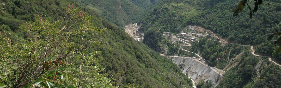
Location
The site of the Lower Mae Ping Dam is located in the Tak province, approximately 50 km north-east of Mae Sot.
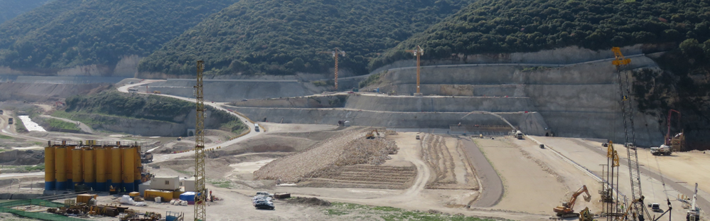
Scope of works
- 2-Phase slurry cut-off wall for cofferdam: 15,500 m²
- Dynamic Compaction: 20,000 m² x 12 m max. depth
- Vibro-compaction: 2,000 m² x 14 m depth
- Secant pile wall as permanent measure, with plastic concrete: 3,500 m²
To increase foundation bearing capacity and stability, dynamic compaction and vibro-compaction were selected.
The dynamic compaction method was executed in 5×5 m pattern by dropping maximum weight of 15 tons from maximum height of 24 m giving a maximum potential energy of 360 ton-meter per drop and carried out in 4 passes and 6 to 25 times of dropping per passes. The results of dynamic compaction by considering the test data from cone resistance greater than 14 MPa show that only 30 % of cone resistance greater than 14 MPa was achieved up to 8 m deep from the surface so vibro-compaction was additionally performed for the deeper part.
The layout of vibro-compaction was equilateral triangular spacing of 2.5 m measured between treatment points or 5 m² per hole. The vibro-compaction method was adopted in the depth between 8 to 13 m from the ground surface.
The 3,200 m² cut-off wall in the form of secant pile wall were constructed as alternating series of interlocking 1,200-mm-diameter unreinforced piles. With this arrangement, the minimum wall thickness amounted to 79 cm. Prior to starting the construction of the secant pile wall, the guide wall was installed parallel to the wall axis. Primary holes were drilled along the guide wall using the hydraulically operated Bauer BG rig to a design depth using double wall casing to pass through alluvial sand and cut in the rock formation about 1.0 m. The secondary piles were commenced when the primary holes had been already filled with plastic concrete for 24 hours. The mix of the plastic concrete comprised 25% of cement, 5% of bentonite and 5% of fly ash. The property of this mix complies with the requirement. The modulus of elasticity of the cut-off wall was designed to be approximately the same as or less than the modulus of surrounding compacted foundation material which was 40 MPa. The permeability of the wall was established at less than 5×10⁻⁸ m/sec.
After having finished with a total of 357 piles, 25 core holes were drilled in the cut-off
wall to check its permeability and the quality of the plastic concrete.
Geological conditions
The dam foundation comprises 20 m thickness of high permeable alluvial sand (8% finer than 0.074 mm) and gravel deposit on bedrock of quartzite and mica schist.
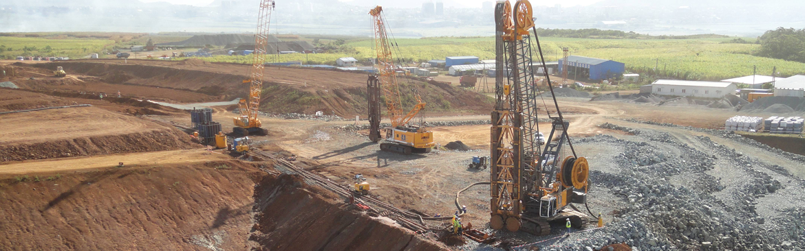
Equipment
- One unit BAUER DHG-A Hydraulic Grab on BS635 Base Crane
- One unit 15t Pounder on 120t NCK Base Crane
- One unit BAUER TR13 Deep Vibrator on BS635 Base crane
- One unit BAUER BG14/30 Drilling Rig
- Continuous feed “2-Phase Slurry” batching/mixing plant (on-site)
Construction period
- Phase 1A: Jun ‘93 to Aug ’93 (temporary cut-off wall for coffer dam)
- Phase 1B: Jan ’94 to Oct ’94 (soil improvement and permanent cut-off wall for main dam foundation)
Phase 2: Jan ’95 to Mar ’95 (temporary cut-off wall for coffer dam)
Bauer Spezialtiefbau
![]()
How to find us
BAUER Spezialtiefbau GmbH
BAUER-Strasse 1
86529 Schrobenhausen
Germany
Phone: +49 8252 97-1178
e-mail: info@bauerdamcontractors.com
Social Media
Copyright © , All Rights Reserved