Feldolling

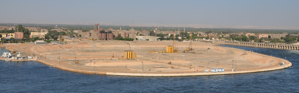
In the area of Feldolling, a village south of Munich, Bavaria, Germany, a flood water retention basin for the river Mangfall is being constructed. In the event of heavy rainfall or seasonal ice-melting in the Alpes, the flood-prone region can suffer from severe damage to the infrastructure and the residential areas. Those events can therefore even threaten people´s lives. The planned flood retention basin will store more than 6 Mio m³ of water. For the construction of the retention basin, the authorities are building a few dikes of different lengths in addition to a dam to capture the flood water in the retention basin.
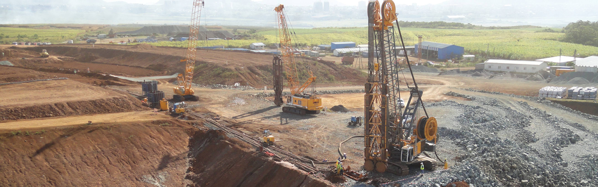
The diaphragm wall executed as a single-phase cut-off wall was installed by deploying a rope grab which excavated under a self-hardening slurry designed by Bauer. A Mixed-in-Place wall (MIP), a deep soil mixing technique, and the jet grouting method were used for the inner sealing and the underground cut-off barrier of one of the dikes.
- Owner: Free State of Bavaria
- Client: Wasserwirtschaftsamt Rosenheim (authority for water resources management)
- Execution: BAUER Spezialtiefbau GmbH in JV with Rädlinger
Location
Feldolling, Bavaria, Germany. Flood control reservoir in lower Mangfall Valley
Scope of Work

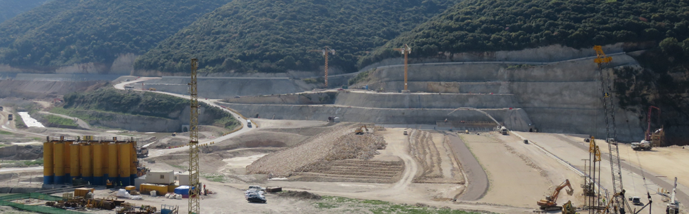
Diaphragm wall (D-wall): single-phase cut-off wall for the sealing of the existing soils under the future dike, of which the top 10 m are reinforced. In total: 6,200 m², with nominal width of 800 mm, and up to 41 m deep. Approximately 800 m² were constructed using the special low headroom equipment under a high voltage (power) line.
Cut-off wall by means of Mixed-in-Place (MIP): the sealing of a dike itself was executed as soil-mixing cut-off wall. In total 21,000 m² with a nominal width of 550 mm, up to 23 m deep.
Besides the execution of the aforementioned cut-off walls, the scope also included the construction of some buildings that are necessary to operate the retention basin during a flood.
Therefore, a bored pile wall (1,700 m², D=880 mm, max. drilling depth: 25 m), several sheet pile walls (3,300 m²; depth down to 14 m), and jet grouting (3,200 m³, max. drilling depth: 32 m) are executed. Both, the Continuous Flight Auger (CFA) and Cased Continuous Flight Auger (CCFA) were applied for the pile construction. CCFA is a combination of the CFA technique with the Kelly method and drill casing, resulting in a cased bore hole, produced by using a continuous flight auger (TRS 620, 880 mm). This method is particularly advantageous in the case of high groundwater and uplift-prone soil layers, which would call for drilling under water load using the Kelly method.
Jet grouting (JG) columns were executed to seal the soil between the cut-off walls and an existing, crossing water pipe (pipe diameter = 1.7m). Final strength of the jet grouting columns, as well regarding single-phase and MIP cut-off walls was limited to within 1 and 3 MPa. To achieve the required strength, a 3-phase method was applied. The technical requirements were fulfilled in all soil layers (clay, silt, and gravelly sands). Circular columns, half columns and sector columns were executed.
Geological condition
According to the soil report, ancient glaciers in that area formed a basin with tertiary subsoils. On top of the tertiary subsoil, glacier movements brought boulders, gravel, and sand. Lakes appeared after the melting of the glaciers and fine-grained soils were washed in and deposited on the ground. Due to heavy movements, growing and reducing size and location of the glacier snout, layers were formed.

Equipment:
- MC 64 duty-cycle crane with rope grab
- RTG RG 27 S Mixed-in-Place unit
- BG 15 in jet grouting configuration
- BG 39 Double Rotary Drilling System
Construction period:
February 2021 – March 2023 (concerning the works of Bauer)
Miscellaneous:
The JV (BAUER Spezialtiefbau and Rädlinger) was also commissioned with the provision of the necessary work platform, the installation and dismantling of the guide wall for the single-phase cut-off wall works, and the project quality control and laboratory testing.
The location of the project poses particular challenges, such as vital utilities crossing the alignment of the cut-off wall. Among these are a gas line, a high-voltage line and a water pipe used for flood management.
Sustainability:
Mixed-In-Place as a construction method, has been proven to allow for a significantly smaller equivalent Carbon Footprint, and for an extremely reduced impact to the neighborhood mainly due to less transports with less traffic required, compared to a classical method based on excavation. To provide clients or other stakeholders with reliable numbers to quantify the specific climate impact of any geotechnical works, available tools are on the market which might contribute to any such sustainability considerations.
Quality assurance:
To ensure the required technical specifications BAUER deployed several measurement techniques. Worth mentioning here are the following:
Mixed-in-Place: inclinometers were installed in 2 of 3 augers to measure the verticality of each panel, which is depicted on the rig operator’s screen in real time. That enables the operator to react to bigger drilling deviations because of unexpected obstacles in the underground. Hence, the rig operator can easily install another panel in the area with bigger deviations, while the slurry is still fresh and maintain the minimum thickness of the MIP wall at the bottom. The combination of using inclinometer to measure the verticality and GPS to get the exact location of each panel at the top makes it possible to depict the as-built for the MIP wall in CAD software and thus prove that the wall has no severe deviations and is installed as per the project specifications.
D-wall: To control verticality and necessary overcut between adjacent panels the Jean-Lutz system was installed in rope grab and applied during single-phase cut-off wall execution.
BAUER b-report quality system was used for two construction methods.
Jet-grouting: during JG works the verticality of each bore hole was checked, and jetting parameters recorded. During the construction of the columns in the immediate vicinity of the drainage pipe a timely analysis was conducted. This procedure enabled a dynamic execution process.
CFA and CCFA: during pile construction the most important parameters like concreting pressure, and volume were checked and recorded.
Bauer Spezialtiefbau
![]()
How to find us
BAUER Spezialtiefbau GmbH
BAUER-Strasse 1
86529 Schrobenhausen
Germany
Phone: +49 8252 97-1178
e-mail: info@bauerdamcontractors.com
Social Media
Copyright © , All Rights Reserved